|
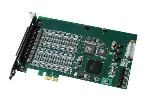
PCI-Express I/O Expansion Cards |
| Existing I/O cards can be easily converted to a true PCI-Express form factor. |
| GSC has numerous I/O cards in true PCI-Express form factor and any I/O card can be easily converted to true PCI-Express.
Also, the large variety of PMC I/O cards from GSC can be used on a PCI-Express adapter.View a list of Adapters.
|
 |
PCIe-to-PMC Adapters | |
GSC has adapters for PMC to PCI-Express, both 1-lane and 4-lane. These adapters are transparent to software and allows a user to
adapt the wide variety of PMC I/O cards to PCI-Express.
View a List of Adapters. |
Data Acquisition |
|
General Standards Corporation is a leading supplier in data acquisition I/O boards, provides a complete family of
data acquisition cards for sonar, industrial, and embedded applications on several form factors/busses, and for many operating systems.
Functions available include analog I/O, serial I/O, and high speed parallel I/O.
|
Form Factors: | |
FREE DRIVERS
AND
LOANER BOARDS |
|
|
|
Software Drivers: |
- Windows
|
- VxWorks
|
- QNX
|
- Linux
|
- MathWorks
|
- Solaris
|
- Labview
|
- xPC Target
|
- Ask About Other Drivers
|
|


- Up to 64 Input Channels per Board
- Programmable Sampling Rates to 50M SPS
- GPS Synchronization
- Auto-Calibration
- Multi-Board Synchronization
- Sigma-Delta and Delta-Sigma Analog I/O
- Resolutions from 12 bits to 24 bits
Analog I/O Selection Tables
- Serial Mode Protocols include Asynchronous, Bisync, SDLC, HDLC, IEEE 802.3, Synchronous Telemetry, Simple Clock/Data ("-SYNC" product line), and Di-phase.
- Transceiver support RS485, RS422, RS232, RS423, V.35, RS530, as well as other software selectable mixed protocol modes
- Up to Eight Independent Serial Channels per Board
- Synchronous Serial Data Rates up to 10 Mbits/sec
- Asynchronous Serial Data Rates up to 1 Mbits/sec
- Deep Transmit and Receive FIFOs up to 128K
- PMC and cPCI rear I/O support
- Custom Protocols Available
Serial I/O Selection Tables
- Cable Transfer speeds up to 400 mb/per second
- Large FPGA provides for flexable cable interface
- Several cable transceiver options including RS-422, RS-485, LVDS, PECL, and TTL
Digital I/O Selection Table
|
PCI Express, officially abbreviated as PCIe is a computer expansion card interface format. It was designed as a much faster
interface to replace PCI, PCIX, and ACP interfaces for computer expansion cards and graphics cards. The PCI Express
(PCIe) physical connection (slot) is completely different from those of the older standard PCI slots or those for PCI Extended
(PCIX).
PCIe is a technology which is a receiving further development and improvement. The initial standard version in general use is
PCIe 1.1; however, PCI-SIG announced the availability of the PCI Express Base 2.0 specification on 15 January 2007. PCIe
2.0 doubles the data rate of each lane from 250 MP/s to 500 MP/s. PCIe 2.0 is still compatible with PCIe 1.1 as a physical
interface slot and from within software, so older cards will still be able to work in machines fitted with this new version. Further
information on PCIe 2.0 is detailed below.
PCIe is backwards-compatible with PCI, and operating systems can boot on the use a PCIe-based system without
modification.
A single PCI Express serial link is a dual-simplex connection using two pairs of wires, one pair for transmit and one pair for
receive, and can only transmit one bit per cycle. Although this sounds limiting, it can transmit at the extremely high speed of 2.5
Gbps, which equates to a burst mode of 320 MBps on a single connection. These two pairs of wires is called a lane.
You can install PCI Express adapters in larger slots but not smaller ones. For example, you can install a PCI Express x1
adapter into an x16 slot (but will still operate at the x1 speed), but you cannot insert an x16 adapter into anx1 slot. This
compatibility is shown in Table 5.3* below.
PCI Express currently runs at 2.5 Gbps, or 200 MBps per lane in each direction, providing a total bandwidth of 80 Gbps in a
32-lane configuration, and up to 160 Gbps in a full duplex x32 configuration.
Future frequency increases will scale up total bandwidth to the limits of copper (which is 12.5 Gbps per wire) and significantly
beyond that via other media without impacting any layers above the physical layer in the protocol stack. The table below
shows the throughput of PCI Express at different lane widths.
*Table 5.3: PCI Express maximum transfer rate Lane width Clock speed Throughput (duplex, bits) Throughput (duplex,
bytes) Initial expected uses:
x1 2.5 GHz 5 Gbps 400 MBps Slot, Gigabit Ethernet
x2 2.5 GHz 10 Gbps 800 MBps
x4 2.5 GHz 20 Gbps 1.6 GBps Slots, 10 Gigabit Ethernet, SCSI, SAS
x8 2.5 GHz 40 Gbps 3.2 GBps
x16 2.5 GHz 80 Gbps 6.4 GBps Graphics adapters
PCI Express uses an embedded clocking technique using 8b/10b encoding. The clock information is encoded directly into the
data stream, rather than having the clock as a separate signal. The 8b/10b encoding essentially requires 10 bits per character,
or about 20% channel overhead. This encoding explains differences in the published spec speeds of 250 MBps (with the
embedded clock overhead) and 200 MBps (data only, without the overhead). For ease of comparison, Table 5-3 shows
throughput in both bps and Bps.
Any PMC I/O board can be used on PCI Express, PCI-X, cPCI-X, PCI, cPCI, PC-104-Plus via an adapter. Our I/O
boards are being converted to PCI Express boards as opportunities arise, view our extensive line of I/O boards.
We have software drivers available for numerous operating systems including VxWorks, Linux, and Windows.
Click Here for more information on software driver availability.
|
|